Received Motor Controller

As I look at this web site I realize I have not updated it in a long time.  But we have still been busy working on the truck.  It just takes twice as long to get stuff done as I think it should.  Originally I hoped I could get it …

more ...

Letting out the smoke, and fire

We burned up the motor controller.  And it was AWESOME.  If you read all the way to the end I promise you a video with some smoke (just a little smoke).

Burned up controller and electronics

more ...

Testing the power board

ANOTHER LONG POST: This post describes 3 weeks of testing that was done with the newly built controller power board.  This is the power board that I wrote about in this post.  We are planning to use this (or at least try it) in the truck if all our testing works out.  For the controller logic board, I am using the Stellaris microcontroller evaluation board for the brains, a partially built DIY controller (see this post) for the analog circuitry, and a plug board for a half-bridge low-side/high-side driver.  So even though the power board is looking good, this whole system is still very much a prototype.  I am working on a circuit design and board layout for the logic part of the controller, but it will be a while before that is finished.

Testing of the power board was done in 3 steps:

  • tested on a bench with a bench supply and limited current
  • tested on the Kart with the battery pack but with no load on the Kart
  • tested using the new controller power board to drive the Kart

Bench testing the new power board with ADC motor

more ...

Building the controller power board

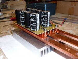
Warning: long post. During February and March we were building the power board. Credit for the mechanical design goes to Brian. I'll detail our experience in making this power board, but first here is a picture of the finished item:

Assembled controller power board

more ...

Prototype Controller Testing Part 3

This week we modified the power circuit, replacing the freewheeling diodes with another MOSFET, and replaced the original MOSFET driver with a half-bridge driver.  Here is the original motor drive circuit, per the ReVolt design (specific part names/values not shown):

Original Motor Driver Design

And here is how we modified it:

more ...

Prototype Controller Testing Part 2

Last week we tried out the "ReVolt" open-source controller for the first time.  At the time, we only had one MOSFET and diode installed.  We were able to spin the small motor at 12V, but when we tried the kart motor at 48V, something popped so we stopped for the evening. This week, with some modifications and a more cautious approach, we were ready to try it again.

Cause of Last Week's "Failure"

First, some commentary on what went wrong last week.  When Bill took apart the power section, he really could not find anything wrong.  At the time we thought that perhaps there was a current spike through the diode as we applied power to the big motor.  But now we think that maybe it was the silver epoxy.  Perhaps there was a high resistance path somewhere that overheated when we started to flow some real current through it.

more ...

Prototype Controller Testing Part 1

Controller board and parts

This post summarizes everything that has been going on the past several weeks.  First, I ordered "Paul & Sabrina's" ReVolt open-source controller board.  Thanks Paul & Sabrina for making this available!  I ordered just the board, not the whole kit.  I ordered the components from Mouser and Digikey.  Insead of using the Atmel microcontroller they specified, I am using a Stellaris evaluation board.  Here is a photo of the blank controller board, the bags of parts and the Stellaris evaluation board.

And here is a photo of the board after most of the parts have been installed.

more ...