It has now been a few years since I did all the electrical wiring in the truck. At the time I created some wiring diagrams for myself so that I would have a map to follow. While not very complex, it is still a lot to just keep in your head. Anyway, I always intended to post my wiring diagrams in case someone else finds them useful. But I did not ever feel like they were presentable and I wanted to clean them up some before making them public. I never did that and recently someone asked me about my wiring diagrams. So I decided to post what I have.
I have done nothing to improve my diagrams but I'll show them here and try to provide some explanation.
HV Wiring
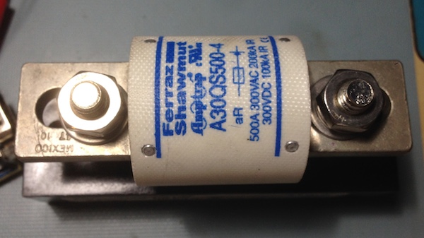
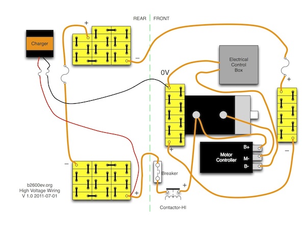
This diagram shows the high voltage wiring in the truck. It is roughly laid out the same way as the physical layout in the truck. On the left side of the diagram is the back of the truck. In the back I have to blocks of cells and the charger. The two cell blocks are of course connected in series, and in between them I have a high current, high voltage DC fuse. It is a Ferraz Shawmut A30QS500-4. I don't remember where I bought it.

High Voltage Fuse
From the two blocks of cells in the back, I run the positive and negative sides up to the front of the truck. I dont have any good photos of this now, but I used flexible conduit that I secured to the frame rails under the truck. They are behind the frame rails, not under so they are really protected from damage as much as possible. And keeping the wire in a conduit protects it from road damage and the elements. The conduits terminate up under the hood in the front, and under the bed in the back. There is nothing directly preventing water getting in the conduit at either end, but the way they are located and arranged there is really no path for water to get in, even if water splashes up under there. I think you would have to deliberately spray water in there to get any water inside.
Of the two blocks of cells in the back, the positive side represents the most positive point of my high voltage battery pack. I connect the positive charging wire (red) to this location. I then run the negative charging lead up to the front of the truck, through another piece of conduit.
The right side of the diagram shows the front of the truck, under the hood. I have two more blocks of cells here to complete the 44 cell traction pack. The one on the left is the "start" of the pack and represents the most negative, or 0 volts point of the traction pack. From there, the HV wiring enters my electrical control box which contains one of two contactors. From there it comes out and connects to B- on the motor controller.
From the highest voltage lead coming from the rear of the truck, it goes first through a circuit breaker. This is a high voltage DC circuit breaker that I acquired through an ebay auction. It is an Airpax JTEP circuit breaker that comes out of telecom equipment power supply cabinets. These are meant for high voltage DC and are supposed to be able to break 10000A. These are a little hard to find and if you just search you will find some at crazy high prices. But if you watch for them on ebay you can eventually find one at reasonable price. Or at least I was able to back in 2011 when I got mine. While I hope this circuit breaker would trip in case of a short, the main reason I have it is to use as a switch so I can disconnect the HV if I need to work under the hood.
By the way, I have a release cable going from the circuit breaker handle to a red "Pull" handle in the cab. So I can open the circuit breaker from inside the cab if necessary.
From the circuit breaker I go through the "high side" contactor and then to the motor and motor controller. The additional fuse that is shown under the hood was never actually installed.
LV Wiring
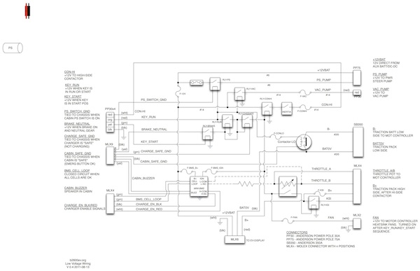
In the HV Wiring diagram above, it shows a "control box". Except for a contactor which carries high voltage, the remaining circuitry in the control box is low voltage. Here is the low voltage diagram:
This diagram is more complicated that the HV wiring. On the left and right sides, and on the bottom, I show connectors that are used to bring signals into an out of the control box. I tried to put some explanatory text by those.
In the middle there are a bunch of relays. These are used for switching 12V power to various accessories. At the top is a relay to switch a power steering pump on and off. There is a brake booster vacuum pump that is turned on whenever the key is in the "run" position (the vac pump is turned off and on with a vacuum switch). There is also some relay logic that requires the brake to be applied before you can "start" the system. So when you turn the key to "run" (the first position) some stuff comes on but the high side relay is not enabled so therefore there is no HV to the system. If you try to turn the key to start, then nothing happens. But if you put your foot on the brake pedal, then turn the key to start, the high side contactor will close and then the HV system is live.
The low-side contactor which is near the right side of the diagram is closed as soon as the key is turned to the run position. This does several things. First it allows the motor controller to precharge. This happens because there is a precharge resistor (not shown in any diagram) that bypasses the high side contactor. So when the high-side contactor is open and the low side is closed, the HV circuit to the motor controller is complete through the precharge resistor. This allows the motor controller to precharge and I can see the voltage on the motor controller because I have a voltage gauge in the cab. Also not shown in either diagram is the DC-DC convertor. But it is wired into the HV system such that when the low-side contactor is closed, the DC-DC turns on and starts supplying 12V. This give me plenty of power at 12V to turn on headlights and run accessories and also will charge the 12V aux battery.
My starting procedure is to turn the key to run and watch the voltage come up on the gauge. When it reaches close to 140V then I press my foot on the break and turn the key to "start". This closes the high-side contactor and now everything is live. Once I do this I can release the brake pedal and the system stays live. The low-side contactor also has a switch in the cab. This is a big red panic button and if I ever press it the low-side contactor will be opened. See this post for a photo of the panic button.
Between the panic button that opens the low-side contactor, and the circuit breaker pull handle, I have two ways to disconnect high voltage from inside the cab.
On the lower right side of the diagram is the motor controller throttle and relay. The throttle potentiometer is of course connected to the motor controller. When the throttle is pressed slightly, a microswitch closes. This is used to turn on the KSI relay (which is a high voltage relay) and enables HV to the motor controller. So, the motor controller does not have any HV applied if my foot is off the throttle.
At the bottom of the diagram is a connector the the EV display. This is a small board that is under the hood, and it has a low voltage cable that goes to an electronic EV display in my dash. This lets me see the battery pack voltage and also tracks state of charge of the batteries.
In the center, lower-left is the Mini-BMS battery monitor. This is wired up to the cell monitoring loop (there is a monitor board on each cell and there is a loop wired in series). If the monitoring loop ever opens, which will happen on cell undervolt or overvolt, then a buzzer in the cab will sound. Some people use this signal to automatically cut back the max throttle or something like that to try to protect the batteries. I decided to not do that and leave it up to the human operator to decide what to do in case the battery alarm goes off. The Mini-BMS also monitors the battery charge and will disable the charger if the voltage goes to high. It also has an interlock so that you cannot continue to charge after a battery alarm until you reset the system.
I know that is a lot of information. I hope it helps some and does not just cause confusion. Feel free to ask questions or point out mistakes.
Thanks for reading.


Comments
There are no comments yet.