This post is about building the motor frame. We worked on this from about June through August of 2010.

Top part of frame fitted onto motor adapter plate
We started off by locating the motor/transmission assembly in the engine compartment using wood blocks to hold it up. We adjusted the position until it seemed like it was in the right location.

Motor propped up in engine compartment
Then we started cutting out pieces of cardboard and fitting them around the motor in order to visualize the design of the frame. We wanted to use the existing ICE motor mount locations. We experimented with several ideas before we arrived at the final design.

Using cardboard to visualize frame design

Prototyping frame design with cardboard
Next, we started cutting the frame pieces. This was an iterative process of cutting a piece, test fitting it, then cutting it or grinding it some more until it was right.

Test fitting motor frame pieces
We started with the top frame. This has a plate that bolts to the motor/transmission adapter plate and is the main structural part of the motor frame.

Getting ready to weld top part of motor frame

Top part of motor frame after welding
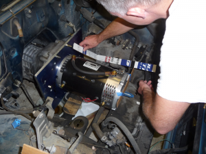
In the photo below, you can see that we have attached the top part of the frame to the adapter plate. If you look closely you can see some metal plate pieces on the motor mounts. We are getting ready to fit struts that will attach the top frame to the motor mounts.

Top part of frame fitted onto motor adapter plate
Once the top frame was complete, then we cut more pieces to use as struts to attach the frame to the motor mounts. In the next photo, we are preparing to tack weld a strut in place.

Preparing to tack weld struts in place
Once the struts were tacked in place, then we removed the entire assembly so we could finish it outside the truck.

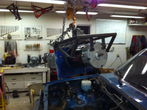
Removing motor assembly so we can finish the frame outside the truck

Removing motor & transmission assembly after motor frame is tack welded
Once it was out of the truck, we added some additional struts to complete the frame and finish welded everything.

Motor frame almost complete, still needs one more set of struts

Test fitting final strut for motor frame
After that we painted it (well, Bruce painted it - thanks Bruce). Then we installed it in the truck.

Finished motor mounting frame installed in truck

Front of motor frame, showing motor hangers
That pretty much wraps up the mechanical work for the electric motor. We will probably have to remove one or two more times, but I think the hard part is done as far as the motor is concerned.
Here is a video that summarizes the work we did to build the motor frame.
Be sure and check back soon when I post a video about THE TEST DRIVE!


Comments
There are no comments yet.