During April and May we worked on the motor-to-transmission coupler and the motor-to-transmission adapter plate. In this post I'll show how we made the coupler and cover the adapter plate in a separate post. Here is a photo of the mostly finished coupler. It has a balancing weight taped on which will later be welded.

Mostly finished motor shaft coupler
Keep reading to see how we made this coupler ...
My truck has a 5-speed transmission. For this electric conversion, I decided to go with a clutchless coupling between the motor and transmission. I talked briefly about the decision to go clutchless in this post. So on one side we have the motor shaft (with keyway) and on the other a splined shaft coming from the transmission. The coupler then must accommodate both of these kinds of shafts. The approach we took is similar to others I have seen on other EV conversion sites, so I can't take credit for inventing it. I posted several links to sites with coupler info in this page about motors and couplers.
We started by removing the splined hub from the clutch plate. This clutch is fairly new, I had it replaced perhaps 20k miles ago. We drilled out the rivets holding the clutch plate together so that the center section could be removed.

Drilling out clutch plate rivets

Clutch center with shock absorbers around hub
This next photo shows the splined hub center with a spider of material that joins it to the rest of the clutch plate. We cut this material off to keep just the hub but I don't have a photo of that.
For the coupler itself, we found a shaft coupler from Grainger that matches on one end exactly the shaft from the motor. The other end has an inside diameter close to what we need to fit the splined hub.
We made a lot of measurements on the transmission to figure out how much space there is between the end of the motor shaft and the transmission shaft to see how long the coupler should be. This coupler is a little longer than we need so we cut part of it off with a band saw.

Shortening the coupler with a band saw
Before welding on the real thing Brian wanted to practice weld so we use this short cut-off piece for test welding. We welded a nut on it and then used a torque wrench to see how much torque it would take to twist it off.

Test welding on spare coupler piece

Nut welded onto spare coupler piece
The next step was to machine out the transmission end of the coupler so that the splined hub will fit.

Machining out end of coupler for hub
After that it was a matter of welding the hub into the coupler. Brian used his TIG welder for this job.
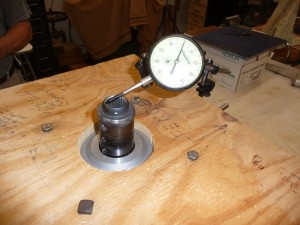
Once we had the welded coupler we spun it on the motor to try to measure the runout and see if it was balanced. It turns out that the center of the splined hub is very well centered with hardly any variation.

Measuring roundness of the hub
However, there was a fair amount of vibration when the hub spins. Thanks to Bill, Brian and Ed for patiently working on finding the right amount of weight and location to balance out the vibration.

Spin testing the coupler (balance weight taped on)
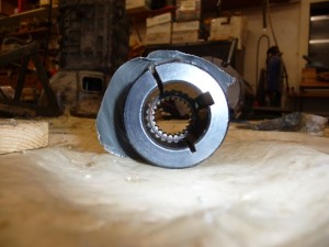
Here is a view of the coupler from the motor end.
And finally, here is a photo of the coupler actually connecting the motor to the transmission from our work on the adapter plate (to be covered in another post).

Coupler inside transmission housing
Here is a short video I made about the coupler fabrication. (Quicktime, ~2 min)
Here is the same video, from YouTube:


Comments
peter
Posted on Fri 26 April 2019
brilliant. just what i'm looking for.
joe
Posted on Sat 27 April 2019
I'm glad it is useful. I do have second thoughts about not using a clutch. Without the little radial springs in the clutch plate, there is nothing to absorb any shock in the drive drain. Most of the time this is not an issue as I drive pretty smooth. But occassionally if I had to suddenly move my foot from throttle to brake (due to traffic or something) there would be a loud clunk as all the play in the drive drain is reversed. If I did it again I would put a lot more thought into a solution that keeps the clutch and perhaps just machining down the flywheel to make it lighter, or something like that.
Good luck with your project.