This site has been stale for a few months, but that doesn't mean that nothing has been happening. In fact we have made quite a bit of progress. In this post I'll cover the fabrication of the adapter plate that goes between the motor and transmission.
Despite the date of this post, the work described here took place in April and May 2010.
We started by making a prototype of the adapter plate using a piece of plywood. This was used just to make sure everything fit the way we wanted, and also to provide a way to test the coupler alignment method (see the post about the coupler).

Plywood adapter plate prototype
Once we were happy with the plywood prototype, we obtained a plate of aluminum and marked it up for drilling.

Marking up the adapter plate for drilling
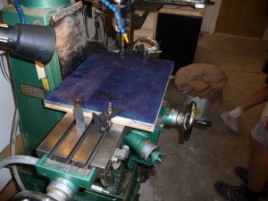
We were going to use the milling machine to cut the center hole, but it turns out that the table was not quite large enough. So we ended up using a hole saw to cut the center hole which was quite a tedious process. We took turns operating the hole saw and even changed out drills because they were getting quite hot. It took a while but the result actually was quite a nice hole that fit perfectly on the motor.

Plate was too big for milling table

Cutting center hole with a hole saw
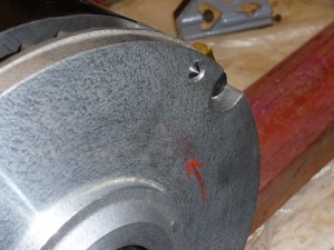
Next, we used a punch threaded into the motor holes to mark the bolt holes for the plate. By pressing the plate up to the motor and using a mallet, we were able to mark the hole locations. Then we drilled the motor bolt holes in the plate.

Using a punch to mark bolt holes

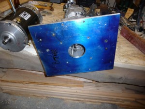
Test fitting the adapter plate to the motor
Given the thickness of the adapter plate, the transmission shaft slightly interferes with the motor shaft. So we had to shorten the transmission shaft. We did this by grinding off the pilot shaft which is no longer needed.
We performed a final alignment of the transmission to the motor and carefully marked the location of the transmission on the plate. Once the transmission was aligned, holes were drilled in the adapter plate for the transmission.

Aligning the transmission and coupler to the adapter plate and motor

Drilling the transmission holes
Once the coupler alignment was completed (see post about coupler), we made some pins that are pressed into the transmission to make sure that it is always assembled with the same alignment.

Test fitting alignment pins in adapter plate

Alignment pins pressed into transmission

Adapter plate as it will be attached to the transmission
Finally we assembled the plate to the motor, then the motor/plate to the transmission. It turns out that the adapter plate is almost a perfect balance point for the whole assembly.

Motor & transmission assembly, almost perfectly balanced at the plate
Here is a video about the adapter plate fabrication and the alignment process.


Comments
There are no comments yet.